2D Drawing Objects in AutoCAD 2010
■ Specify drafting settings
■ Draw a circle
■ Draw a polygon inscribed in a circle
■ Apply a hatch pattern to a closed boundary
■ Draw an arc
■ Draw a polyline
Tutorial Files
1 Download the drawing_objects.zip file from
http://www.autodesk.com/autocad-tutorials.
2 Unzip drawing_objects.zip to C:\My Documents\Tutorials
Specify Drafting Settings
1 To open AutoCAD, click Start menu (Windows) ➤ (All) Programs ➤
Autodesk ➤ AutoCAD 2010 ➤ AutoCAD 2010- English. The AutoCAD
window opens with an empty drawing file named Drawing1.dwg.
2 Check the status bar to make sure you are in the 2D Drafting &
Annotation workspace.
3 To complete subsequent lessons in this tutorial, you must specify some
drafting settings. Right-click the Object Snap icon in the status bar at the
bottom of the window, and select Settings.
4 The Drafting Settings dialog box is displayed. In the Object Snap tab,
make sure the Object Snap On option is selected. Also, select Endpoint,
Midpoint, and Center for the Object Snap modes. Make sure the other
options are not selected. Select OK.
Draw a Circle
In this lesson, you learn how to draw a circle by specifying the center point
and radius.
To draw a circle
1 With Drawing1.dwg open, on the ribbon, click Home tab ➤ Draw panel
➤ Circle drop-down menu ➤ Center, Radius .
2 Drag the crosshairs cursor down to the drawing area.
3 Click the left mouse button to specify the center of the circle.
4 The dynamic input prompt asks you to “Specify radius of circle.” Enter
3.25 from the keyboard and press the Enter key to create a circle with a
radius of 3.25.
Draw a Polygon
A polygon is an equilateral closed polyline with between 3 and 1024 sides.
Creating polygons is a simple way to draw equilateral triangles, squares,
pentagons, and hexagons.
In this lesson, you learn how to create a polygon inscribed in a circle.
To draw a polygon
1 On the ribbon, click Home tab ➤ Draw panel ➤ ➤ Polygon.
2 Drag the cursor down to the drawing area. In the dynamic prompt, use
the keyboard to enter 6 to specify the number of sides of the polygon.
Press Enter.
3 The dynamic prompt changes to “Specify center of polygon.” Move the
cursor inside the circle to find its center point. Click when you see the
orange circle and the dynamic cursor “center”, which indicates the center
of the circle.
4 The dynamic prompt changes to “Enter an option” and you have a choice
of two options. Click the Inscribed in circle option.
5 The dynamic prompt changes to “Specify radius of circle.” Enter 3.25
and press the Enter key to specify the radius of the inscribed circle. You
have created a six-sided polygon inscribed within a circle.
Apply a Hatch Pattern
You can fill a closed boundary with a predefined hatch pattern; a simple line
pattern using the current linetype; or a custom hatch pattern. One type of
pattern is called solid, which fills an area with a solid color.
To use a predefined hatch pattern
1 On the ribbon, click Home tab ➤ Draw panel ➤ Hatch.
2 In the Hatch and Gradient dialog box, click Add: Pick Points.
3 Click inside the polygon to select it. Do not select an edge of the polygon.
Press the Enter key.
4 In the Hatch and Gradient dialog box, Hatch tab, under Type and Pattern
group box, specify the following using the drop-down menu:
■ Type: Predefined
■ Pattern: Steel
5 Click OK. The selected hatch pattern is applied to the polygon.
6 Click ➤ Save, and then close the drawing.
Draw an Arc
you learn how to create a curved object called an arc.
To draw an arc
1 Click ➤ Open.
2 In the Select File dialog box, browse to C:\My Documents\Tutorials\ and
select the bolt_add_arc.dwg file.
3 Click Open. In this lesson, you will finish the side view drawing of a bolt
by adding an arc.
4 To make it easier to add the arc, zoom in on the bolt and pan to bring it
into view.
5 On the ribbon, click Home tab ➤ Draw panel ➤ 3-Point.
6 Drag the cursor down to the bolt drawing and go to the location indicated
by the colored square in the following figure. The word “endpoint” will
appear in the dynamic input cursor.
7 Click near the center of the colored square. This is the first point of the
arc. The square is a visual cue that helps you “snap” to the exact endpoint
of the existing line. This feature allows you to create precise drawings.
8 Move the cursor away from the first point. Next, you will enter the
location for the second point, as well as the arc angle. Both of these are
entered using the dynamic input prompt.
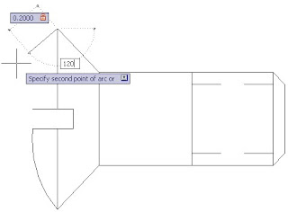
9 First, use your keyboard to enter 0.2000 for the second point of the arc.
Notice that this value appears in the dynamic input box. Do not press
Enter. Instead, press the Tab key on your keyboard.
10 The tab key takes you to the dynamic input prompt for the arc angle.
Enter 120. Press Enter to complete the second point of the arc.
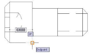
11 Move the cursor down to the location shown in the following figure.
When the colored square appears and “endpoint” appears in the dynamic
input cursor, click in the center of the square to complete the arc.
Draw a Polyline
you learn how to create an object called a polyline. A polyline
is a sequence of segments created as a single object. Polylines can contain
both straight and curved segments. In this lesson, you learn how to draw a
polyline with straight segments.
To draw a polyline
1 Click ➤ Open.
2 In the Select File dialog box, browse to C:\My Documents\Tutorials and
select the bolt_add_polyline.dwg file.
3 In this lesson, you will finish the side view drawing of a bolt by adding
polylines.
4 On the ribbon, click Home tab ➤ Draw panel ➤ Polyline.
5 Drag the cursor down to the bolt drawing and go to the location indicated
by the colored square in the following figure:
6 Click near the center of the colored square. This is the first point of the
polyline.
7 Drag the cursor to the location indicated by the colored square in the
following figure:
8 Click near the center of the colored square. You have drawn the first line
in the polyline.
9 Drag the cursor to the location indicated by the colored square in the
following figure:
10 Click near the center of the colored square. You have drawn the second
line in the polyline.
11 Drag the cursor to the location indicated by the colored square in the
following figure:
12 Click near the center of the colored square. You have drawn the third
line in the polyline.
13 Press the Enter key to end the polyline.
14 Click on one of the line segments of the polyline to select it. Notice that
when you select one line segment, the entire polyline is selected.
15 Click ➤ Save, and then close the drawing.


