Google Search

Loading

Wednesday, September 15, 2010

Lesson 3: Work with Dimensional Constraints

Learning Objectives
On completing this lesson, you will be able to do the following


■ Describe dimensional constraints.

■ Create aligned and angular constraints.

■ Change a design by changing the values of the dimensional constraints.

■ Plot dimensional constraints for design reviews, and understand the
differences between dynamic and annotational constraints.

Command: DIMCONSTRAINT


Dynamic dimensional constraints control the lengths, radial sizes, and angles
of objects. They also control the distances between objects or points on objects.
For example, in addition to controlling the lengths of selected objects, you
might want to keep the distance between lines constant, such as the tread
length of stairs.

Let’s apply dynamic constraints to the drawing of the deck plan.

To create dynamic constraints


1 Open the drawing file, PD_Deck3.dwg.

This drawing is the deck plan with all the geometric constraints applied
Let’s verify that the geometric constraints are applied.

2 On the Geometric panel, click Show All to display all geometric
constraints.


3 On the Geometric panel, click Hide All.

4 On the Dimensional panel, click Aligned.


5 At the Command prompt, press Enter to specify the Object option.

6 Select the horizontal line as shown and then click a location for the
dynamic constraint.


7 Press Enter or click anywhere outside the box to accept the current length
of the line.


This step provides the opportunity for you to change the length of the
line.

8 Click Aligned again.

9 Create an aligned constraint for the bottom horizontal line as shown.
You will need the extra space later.


10 Create two more Aligned constraints on the vertical lines as shown.


You might wonder why we did not apply Horizontal and Vertical
constraints instead of the Aligned constraints. For this design, we want
to control the lengths of the lines. The Horizontal and Vertical constraints
control only the horizontal and vertical distances.
 This distinction is important when you work with diagonal lines or later need to rotate a
drawing.


11 Zoom into the area of the stairs.
We will apply constraints on the tread length for each step.

12 On theDimensional panel, click Aligned.

13 Click the vertical line as shown, making sure that you see the endpoint
glyph.


14 Click the endpoint of the vertical line to the left, and click a location for
the constraint.


15 Press Enter or click anywhere outside the box to accept the value of 45.

16 Create an Aligned constraint between the next pair of lines as shown.


17 Repeat the process for the last pair of lines as shown.


Each of the endpoints of these lines will now maintain a distance of 45
cm from each other, and the parallel geometric constraints will keep the
lines parallel.


18 On the Dimensional panel, click Angular.

19 Click the two lines in the corner of the deck as shown.


20 Click a location for the constraint, and press Enter or click anywhere
outside the box to accept the value of 90 degrees.
Later, you will see why we chose to use an Angular constraint for this
corner.

21 Zoom out until you can see the entire deck plan as shown.


Now that we have fully constrained this deck design, let’s change some
of the parameters. There are several ways to do this.


To change dimensional constraints

As mentioned previously, before you modify a constrained design, it’s often
a good idea to apply one or more Fix constraints first. This keeps those objects
from shifting or rotating. You can always delete the Fix constraints later.

1 Turn on the display all Geometric constraints and verify that the two Fix
constraints are applied. Then turn off the display of all Geometric
constraints.

2 Double-click the d1 dynamic constraint as shown.


3 Click within the edit box and enter 1000 as the new value.
The entire deck was shortened slightly. Next, we will try to make the deck
plan a little less boring.

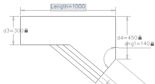
4 Double-click the ang1 dynamic constraint as shown.


5 Click in the edit box and enter 120 as the new value.


This design is more interesting, but still too timid. Let’s make the angle
larger.

6 Change the value of the ang1 dynamic constraint to 140.


This design is much more interesting. You might want to experiment
with other values.


7 Close the drawing without saving it.

To plot dimensional constraints
Dynamic constraints do not have the same purpose as the dimensions in a
construction document or a manufacturing drawing, nor do they maintain
typical dimensioning standards. Thus, dynamic constraints are not plotted
with the rest of the drawing. However, you might want to plot them for design
reviews. In those circumstances, you can change dynamic constraints into
annotational constraints.

Annotational constraints are plotted, have a static size, and use the current
dimension style.


1 Open the Properties palette.

2 Select a dynamic constraint.

3 In the Properties palette, under Constraint, select Annotational from the
Constraint Form drop-down list.


The resulting annotational constraint uses the current dimension style.

4 Close the Properties palette.

5 (Optional) Plot your drawing to a plotter or a printer.

Summary


You have learned how to apply dimensional constraints and how they work
with geometric constraints to control a design. You also learned how to change
designs by changing the values of dimensional constraints. Finally, you learned
how to change dynamic constraints into annotational constraints for plots
to be used in design reviews. Next, you will learn how to add formulas and
expressions to a design.


Review Questions


1 What is the most commonly used dynamic dimensional constraint that
controls the lengths of objects or the distances between them?


2 How can you change the value of a dimensional constraint?


3 What is the purpose of a Fix constraint?


4 What must you do to create a plot that displays dimensional constraints
for a design review?


Saturday, September 11, 2010

Lesson 4: Control a Design Using Parameters and Expressions


Learning Objectives

On completing this lesson, you will be able to do the following::


■ Incorporate formulas and expressions, and manage them with the
Parameters Manager.

■ Create and name user variables.

File Name: PD_Deck4.dwg, PD_Areas.dwg

Command: PARAMETERS, -PARAMETERS


You can modify dimensional constraints and user variables either directly or
with the Parameters Manager

To rename dimensional constraints

Let’s change some dynamic constraints to use more descriptive names.

1 Open the drawing file, PD_Deck4.dwg.


2 Double-click the dynamic constraint, d1, and change the d1 to Length
as the new name.

3 Press Enter or click outside the edit box to accept the change.


Another way to change the name of a dynamic constraint is to use the
Parameters Manager.

4 On the Parametric tab, Manage panel, click Parameters Manager.


5 In the Name column, double-click d2 and enter Width.

6 Press Enter or click outside the edit box to accept the change.

To define a user variable


Often, it is convenient to make a single change that affects multiple dynamic
constraints. For example, you might want to experiment with several tread
widths for the steps in the deck plan.

1 Double-click an empty row in the Parameters Manager.


2 Change the name of the new user variable from user1 to Tread.


3 Press Enter or click outside the Parameters Manager palette to accept the
new name.

4 Change the value in the Expression column from 1 to 45.


5 Press Enter or click outside the Parameters Manager to accept the new
value.

6 In the Expression column of d5, d6, and d7, enter Tread.


These changes associate the value of each of these distances with the user
variable, Tread. Let’s test your control over the tread widths


7 In the Expression column of the user variable, Tread, change the value
from 45 to 60. Then change it to 40.

The changes are updated automatically in the deck plan.

8 Close the drawing without saving it.

To create dimensional relationships between objects


The Expression column in the Parameters Manager can contain constants,
references to dynamic constraints, references to user variables, arithmetic
operators, and functions. Consider the following example.

1 Open the drawing file, PD_Areas.dwg.


This is a fully constrained drawing of a rectangle with a circle at its center.
The circle always has the same area as the rectangle. Let’s examine the
dynamic constraints in detail.


2 On the Geometric panel, click Show All and then Hide all to confirm
that geometric constraints have been applied.


3 If necessary, open the Parameters Manager

4 In the Parameters Manager, click the Length row.


As long as your cursor is in the Parameters Manager, the Length dynamic
constraint remains highlighted in the drawing. Length is set to the constant
60.

5 Click the Width row and observe the highlighted dynamic constraint.


To center the circle, the d1 and d2 dynamic constraints are defined as
Length/2 and Width/2. The user variable, Area, is defined as the product
of Length and Width, the area of the rectangle.

6 Click the Radius row.


The radius of the circle is defined with the expression containing the area
of the rectangle, the square root function, and the constant, PI. This sets
the radius of the circle to a value that constrains the area of the circle to
be equal to the area of the rectangle.


Notice that you can store expressions in a dimensional constraint or in
a user variable. A full list of available functions is documented in the
AutoCAD User’s Guide Help topic, Constrain a Design with Formulas and
Equations.


7 Experiment by changing the values for the length and width of the
rectangle.


Notice that the Value column displays the current value of the expression
in the Expression column. Are you curious what would happen if you set
the length of the rectangle to 0 or -1?

8 Close the drawing without saving it.

Summary


You have learned how to incorporate mathematical expressions in dimensional
constraints and in user variables with the Parameters Manager. These tools
provide a method for completely controlling the shape, size, and proportions
of a design.


Review Questions


1 What are the two places within a parametric drawing that you can store
a formula?


2 How can you display a list of user variables in a drawing?


3 What is the purpose of the Value column in the Parameters Manager?


For more information about working with the Parametric Drawing feature,
see the AutoCAD User’s Guide. Help topic, Design with Parametric Constraints.


Wednesday, July 14, 2010

Supported operating systems for the Auto Cad 2010

System Requirements

For 32-bit AutoCAD 2011

  • Microsoft® Windows® 7 Enterprise, Ultimate, Professional, or Home Premium (compare Windows 7 versions); Microsoft® Windows Vista® Enterprise, Business, Ultimate, or Home Premium (SP1 or later) (compare Windows Vista versions); or Microsoft® Windows® XP Professional or Home edition (SP2 or later)
  • For Windows Vista or Windows 7: Intel® Pentium® 4 or AMD Athlon® dual-core processor, 3.0 GHz or higher with SSE2 technology; for Windows XP: Intel Pentium 4 or AMD Athlon dual-core processor, 1.6 GHz or higher with SSE2 technology
  • 2 GB RAM
  • 1.8 GB free disk space for installation
  • 1,280 x 1,024 true color video display adapter 128 MB or greater, Microsoft® Direct3D®-capable workstation-class graphics card
  • 1,024 x 768 display resolution with true color
  • Microsoft® Internet Explorer® 7.0 or later 
  • Install from download or DVD

For 64-bit AutoCAD 2011

  • Microsoft Windows 7 Enterprise, Ultimate, Professional, or Home Premium (compare Windows 7 versions); Microsoft Windows Vista Enterprise, Business, or Ultimate (SP1 or later) (compare Windows Vista versions); or Microsoft Windows XP Professional (SP2 or later)
  • AMD Athlon 64 with SSE2 technology, AMD Opteron® processor with SSE2 technology, Intel® Xeon® processor with Intel EM64T support and SSE2 technology, or Intel Pentium 4 with Intel EM64T support and SSE2 technology
  • 2 GB RAM
  • 2 GB free space for installation
  • 1,280 x 1,024 true color video display adapter 128 MB or greater, Microsoft® Direct3D®-capable workstation-class graphics card
  • 1,024 x 768 display resolution with true color
  • Internet Explorer 7.0 or later 
  • Install from download or DVD

Additional Requirements for 3D Modeling (All Configurations)

  • Intel Pentium 4 processor or AMD Athlon, 3 GHz or greater; or Intel or AMD dual-core processor, 2 GHz or greater
  • 2 GB RAM or more
  • 2 GB hard disk space available in addition to free space required for installation
  • 1,280 x 1,024 true color video display adapter 128 MB or greater, Pixel Shader 3.0 or greater, Microsoft® Direct3D®-capable workstation-class graphics card

Modify Object Properties by Layers

you learn to change the default and assigned properties of a
layer. You change the color, linetype, and lineweight of layers.
To change the linetype assigned to a layer
1 Ensure that the Layer Properties Manager is open. Click in the Linetype
column of the Green Gas layer.
2 In the Select Linetype dialog box, select a linetype from the listed options.
If the linetype you need is not listed, click Load.

3 Select the HOT_WATER_SUPPLY linetype and click OK.
The selected linetypes are loaded.

4 Select the HOT_WATER_SUPPLY linetype and click OK.
Objects on the layer are updated to the HOT_WATER_SUPPLY linetype.

You have learned to change the linetype for a layer.

To change the color assigned to a layer

1 Ensure that the Layer Properties Manager is open. Click in the Color
column of the Green Gas layer.

2 In the Select Color dialog box, the Index Color tab, select the Red color
swatch and click OK. The object in the layer is updated to red color.
Objects on the layer are updated to the color red.

You have learned to change the color for a layer.

To change the lineweight of a layer

1 Ensure that the Layer Properties Manager is open. Click in the Lineweight
column of the Green Gas layer.
2 In the Lineweight dialog box, Lineweight list, select the lineweight 0.70
mm and click OK.
Objects on the layer are updated to the lineweight 0.70 mm.
You have learned to change the lineweight of a layer.

Saturday, April 10, 2010

Creat Basic 3D Object in Auto Cad 2010

This tutorial outlines the procedures for creating three-dimensional objects by creating basic
3D shapes known as solid primitives. You can also create 3D models by extruding 2D shapes.
Audience: Users new to 3D modeling with AutoCAD 2010
Prerequisites: Working knowledge of 2D drafting
Time to complete: 15 minutes
Objectives
■ Create 3D solid primitives
■ Create 3D objects from 2D objects


Create 3D Solid Primitives

In this lesson, you learn how to create 3D solid primitives in the 3D Modeling
workspace.
You can use standard 3D solid objects known as solid primitives to create a
box, cone, cylinder, sphere, torus, wedge, and pyramid. To create these 3D
solid primitives, switch the workspace to 3D Modeling, where the palettes
and ribbon panel are customized to create and modify 3D solid models.
Switch to the 3D Modeling Workspace
1 On the status bar, at the bottom of the drawing area, click the Workspace
Switching button.
2 On the Workspace menu, click 3D Modeling.

Get Started Auto Cad 2010

In this lesson, you learn how to start AutoCAD. You also learn about the basic
areas of the AutoCAD window.
To download tutorial file
1 Go to http://www.autodesk.com/autocad-tutorials.
2 Unzip getting_started_basics.zip to C:\My Documents\Tutorials.
To start AutoCAD
1 To open AutoCAD, click Start menu (Windows) ➤ (All) Programs ➤
Autodesk ➤ AutoCAD 2010 ➤ AutoCAD 2010 - English.
NOTE If the New Features dialog box appears, select Maybe later and OK
to close it.
The AutoCAD window opens with an empty drawing file named
Drawing1.dwg.
2 Before moving on to the next lesson, become familiar with the areas of
the AutoCAD window labeled below.

Use a Drawing Template

In this lesson, you learn how to start a drawing using a drawing template file.
When you use a template file, new drawings created from the template
automatically use the settings defined in the template. This saves you setup
time and helps to make sure each drawing you create follows your company’s
CAD standards.
Drawing template files have a .dwt file extension
Some of the settings stored in drawing template files include
■ Unit type and scale (precision)
■ Title blocks/borders, blocks, and logos
■ Layer names
■ Snap, grid, and ortho settings
■ Grid limits
■ Annotation styles
■ Linetypes
To start a drawing with a template
1 Click Start menu (Windows) ➤ (All) Programs ➤ Autodesk ➤ AutoCAD
2010 ➤ AutoCAD 2010 - English.
2 NOTE If the New Features dialog box appears, select Maybe later and OK
to close it.
The AutoCAD window opens with an empty drawing file Drawing1.dwg.
3 Click ➤ New.
4 In the Select Template dialog box, select Tutorial-iArch.dwt.

5 Click Open to open the Tutorial-iArch.dwt template.